The design of high-speed POL cannot be achieved just by simply increasing the oscillation frequency.
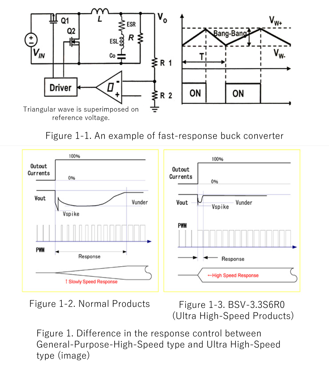
When the load has suddenly changed, the change at the output is detected and the pulse width is controlled via modulation circuit in the conventional negative feedback circuit using pulse width modulation (PWM) but the modulated signal is gradually propagated due to the delay in phase in the error amplifier and controlled as shown in Figure 1-2.
During the uncontrolled period, the output voltage is held by the charges in capacitor C0.
Therefore, when a sudden current flows into the load, the capacitor discharges and current flows to the output, and the response waveform will be determined by the “Small” or “Large” of the equivalent series resistance (ESR) and lead inductance (ESL) of the capacitor.
The ΔVout at the time is;
ΔVOUT = ΔVCout + ΔIOUT x RESR
The Bang-Bang control method enables the realization of a fast response circuit. In the circuit shown in Figure 1, a hysteresis comparator is used but no error amplifier is used. By this reason, the control speed is faster as there is no delay in phase in the error amplifier. The hysteresis comparator is controlled by applying the voltage of a triangular wave superimposed on the reference voltage to the positive terminal of the comparator IC and comparing the voltage at R1 and R2 that detect the change in the output voltage, Vout. (Figure 1-2).
Figure 1-3 shows the PWM control waveforms of an Ultra-High Speed POL converter. The high-speed type detects steep load changes and performs high-speed control by responding to the 1st pulse.
Written by SHOTARO SUZUKI