1. Overview
As isolated DC-DC converters are isolated between the primary side and secondary inside the converter as shown below, output polarity reversal and series connection are possible.
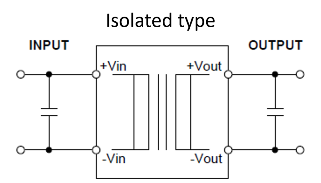
Fig.1
2. Polarity reversal
2-1. Isolated, Positive output : Ex) From +12V to +5V
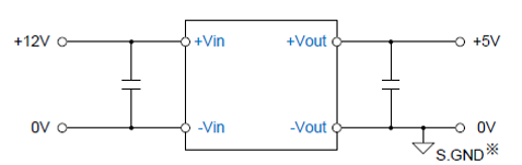
Fig.2
2-2. Isolated, Negative output : Ex) From +12V to -5V
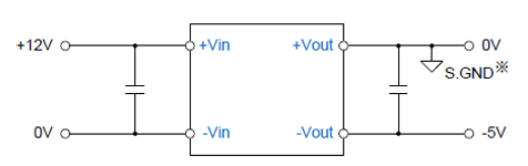
Fig.3
※S.GND … Secondary side ground
2-3. Non-isolated, Positive output : Ex) From +12V to +5V
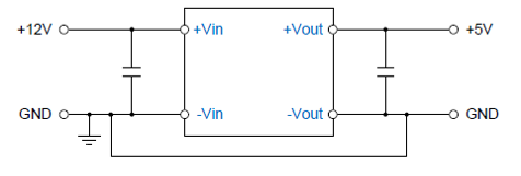
Fig.4
2-4. Non-isolated, Negative output : Ex) From +12V to -5V
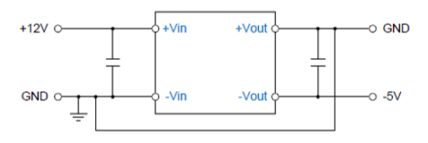
Fig.5
3. Series connection
As the series connection is related to the isolation voltage of the converter, please contact us when connecting 3 units or more just in case.
3-1. From 2 single outputs to +/- dual outputs : Ex) From +5V to +/-12V (From two +12V output converters to +/-12V outputs)
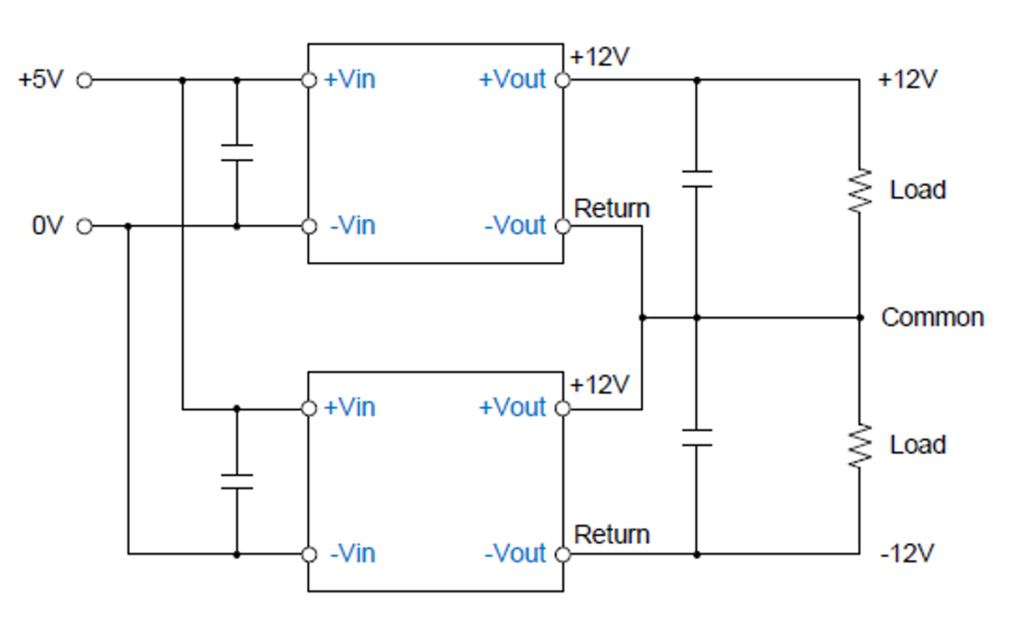
Fig.6
No diodes are required between + Vout and Common and between Common and -Vout.
3-2. From two single outputs to double voltage outputs : Ex) From +5V to +24V (From two +12V output converters to +24V output)
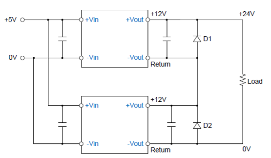
Fig.7
Two converters can be used in this way even if those are not the same on output power and/or output voltage. In that case, the smaller value of those two converters is applied on the maximum load current.
Insert a diode (D1, D2) between each output to prevent startup failure.
Conditions for Diode (D1, D2) selection
Forward voltage: Selecting the minimum Vf diode is ideal, therefore, a Schottky barrier diode is recommended.
Reverse voltage: Should at least be as twice as the voltage difference between + Vout and – Vout of each converter.
Forward current: Should be the maximum output current of each converter or larger. (Derating and other factors should be taken into consideration.)
Reverse current: As a voltage is applied to the diode all the time when the converter is working, it is recommended to select the one that leakage current is the minimum.