A switching DC-DC converter is made by combining a pulse width control method called PWM (Pulse Width Modulation) and a negative feedback amplifier. Speed, temperature, lighting, etc. that always “keep the conditions constant” are the same negative feedback control as the power supply.
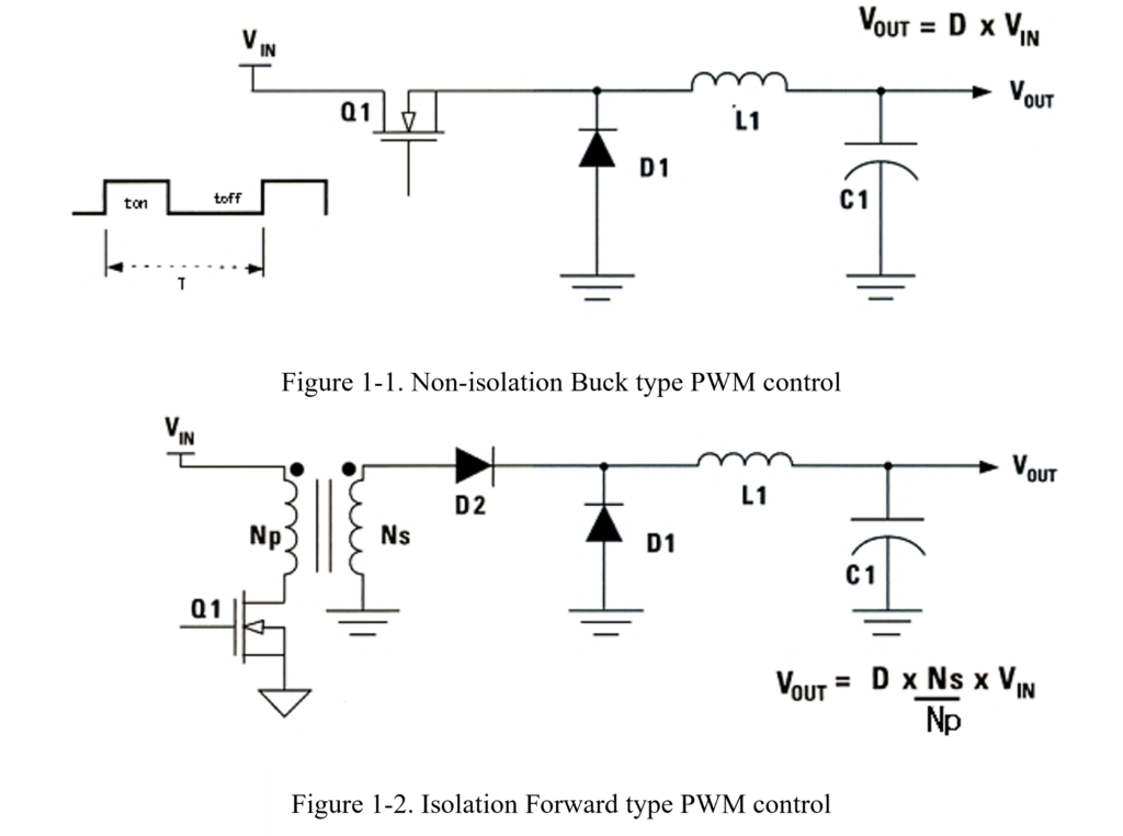
Figure 1-1 shows the basic circuit of a buck-type step-down, PWM-controlled DC-DC converter.
Constant voltage control is performed by changing ton / toff with respect to the fixed oscillation period T. When Q1 is ON, the current is smoothed by the inductor L1 and the capacitor C1, and the constant voltage control is continued by the pulse width control.
Figure 1-2 shows an isolated forward converter.
Take a closer look at both Figure. In fact, both have the same circuit system. In Fig. 1-2, the power MOSFET in Fig. 1-1 is configured via an isolation transformer, and the control operation is basically the same for the step-down PWM converter and the forward converter.
Thinking in this way, if you study the step-down converter shown in Fig. 1-1 thoroughly, it will be easier to understand both the forward converter and active clamp control.
How is pulse width modulation done? It is made using a comparator circuit. The comparator circuit is the basis of the pulse width modulation circuit.
Written by Shotaro Suzuki